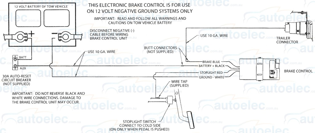
Reese Trailer Brake Wiring Diagram. In the electric system the braking system consists of brake controller, stoplight wire, battery, hydraulic connection, master cylinder, power wire, variable resistor (optional), brake wire. As drivers slow down behind a vehicle that is pulling a trailer, they will often instinctively focus on the bright brake lights as a reference point for.
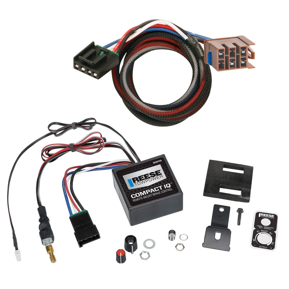
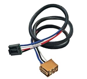
For brake controls with wiring port built into back of unit.
The trailer has electric over hydraulic brakes.
HAYMAN REESE ELECTRONIC CARAVAN TRAILER ELECTRIC BRAKE ...

Hayman Reese Trailer Plug Wiring Diagram | Trailer Wiring ...

Reese Trailer Light Wiring Harness T-One Connector Brake ...

Pilot Trailer Brake Controller Wiring Diagram Creative ...
Amazon.com: Reese Towpower 78050 Brake Control Wiring ...

Brake Force Trailer Brake Controller Wiring Diagram Top ...

Utility Trailer Wiring Diagram With Brakes | Trailer ...

Reese Trailer Brake Controller Wiring Diagram - Wiring Diagram

Reese Trailer Brake Controller Wiring Diagram - Hanenhuusholli
Referring back to the brake controller wiring diagram, all connections are made directly to the car's battery. Having the various pinout diagrams available is vital to troubleshooting and/or. Not sure which wires attach to what on your trailer connectors?